In this tutorial, we will demonstrate a simple framework for home automation to control appliances or devices around your home remotely, up to a range of about 10-20ft using a Raspberry Pi, 433Mhz frequency radio transmitter and Etekcity remote outlets.
The 433Mhz radio frequency band is an Ultra High Frequency (UHF) band in which license free communication devices are allowed to operate – typical devices are remote control switches and garage door openers. Based on my research the FCC rules around operation are mentioned here.
We will use an inexpensive 433Mhz transmitter chip to control a 433Mhz radio relay switch – in our case the radio relay is Etekcity remote outlet. For this first we need to read the signal being sent for on and off by the Etekcity remote to the outlets using the receiver chip and then transmit the same commands using transmitter chip connected to the Raspberry Pi.
Components:
- Raspberry Pi
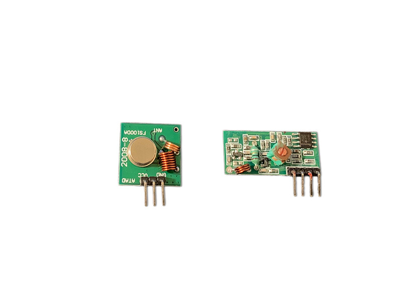
- 433 Mhz Transmitter and Receiver Chips.
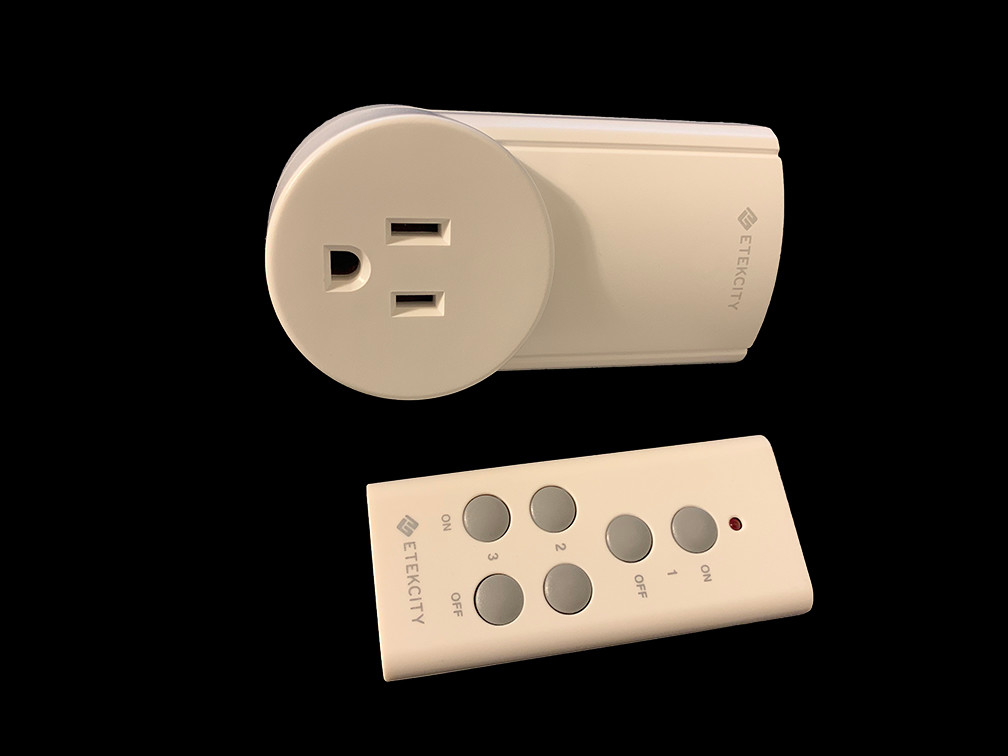
Major retailers such as Amazon, Sparkfun and Adafruit sell these. I found a Sparkfun datasheet here. Based on the datasheet and the following converter, operating at 3.3V Vcc (from Pi), the transmitter should have EIRP of 4dbm approx and produce field strength of approx 100microvolt/m for 3m, which is well below the limits speicifed in FCC rules. The other rules to comply with during transmission are mentioned of the link provided above. - Etekcity remote outlets (These cost around $20, the box has 3 outlets and a remote with on/off buttons)
- A lamp to connect to remote outlet
- Python library called rpi-rf
Hardware Connections
a. Raspberry Pi and 433Mhz Chips
First completely shut down the raspberry pi, we recommend disconnecting it from the power source before making the connections.
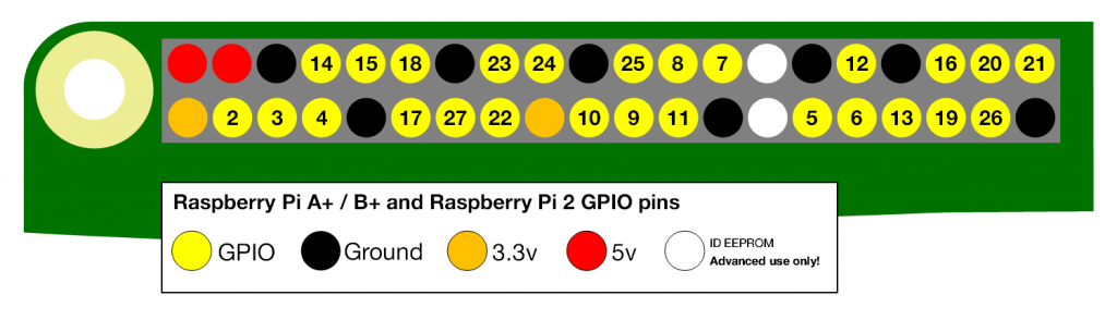
Carefully connect the 433Mhz chips to Raspberry Pi GPIO as shown in the diagrams below:
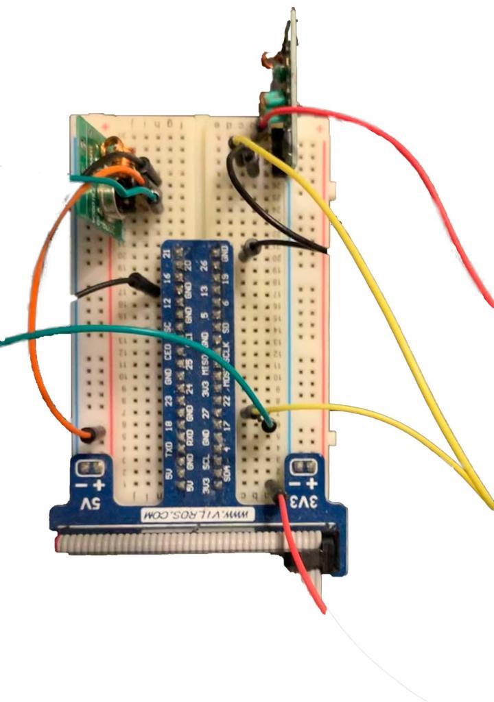

We have connected the data pin of 433Mhz transmitter chip to pin 17 of the Raspberry Pi and the receiver chip data pin to the pin 27 of the raspberry pi.
After doing this setup boot the raspberry pi up.
b. Etekcity outlet and lamp
Also remember to connect the lamp to one of the Etekcity outlets, note the number of the outlet from your set (i.e. 1, 2 or 3) you will be using the remote to turn this outlet on and off.
Plug the Etekcity outlet into an electrical socket.
Python setup
Install the raspberry pi radio library which makes this project extremely easy, on the terminal console of Raspberry Pi type the following command:
pip3 install rpi-rf
We are assuming that you know how to log into your Raspberry Pi and do basic setup if not then read this page first.
This installs the rpi-rf library used to control the 433Mhz radio chips.
Next copy the rpi-rf_receive script from below:
https://github.com/milaq/rpi-rf/tree/master/scripts
Save it as rpi-rf_receive.py, and transfer it on to the Raspberry Pi – you can use WinScp or VNC to transfer the script on to Raspberry Pi.
Then run the script using the following command on your Raspberry Pi:
python3 rpi-rf_receive.py
In our setup we had by default connected the data pin of receiver to pin27 which is the default pin of the script, if you have connected it to some other pin then specify the pin number using the following command:
python3 rpi-rf_receive.py –g 22
Here the command specifies pin 22 as non-default pin.
Demo Video:
Calibration and Testing
Once the receive script is running, press the ‘ON’ button on the remote corresponding to the outlet you have connected and you should see an output on your screen reading the code, pulse and protocol. In our experience if the receiver radio chip is faulty or if there is too much electrical or radio noise around the chip then it picks up a lot of noise and you will see random numbers pop-up on screen, but if the chip is working correctly it will only pick up the 433Mhz frequency number once the button is pressed.
As soon as you see the code, pulse length, protocol on screen, press the buttons few more times to confirm the values and then note these down on a piece of paper, note the remote has two buttons – one for on and one for off, so you will need to record both the codes.
Now it is time to send these codes without the remote, using just the Raspberry Pi and 433Mhz transmitter chip, and observe the output. We found that the author of the rpi-rf library has added few more parameters to his send script which are a little confusing, so we will use the following simple script to test sending the code:
Name: sendRf.py
from rpi_rf import RFDevice
rfdevice = RFDevice(17) #default gpio pin
rfdevice.enable_tx()
rfdevice.tx_code(7689485, 1, 170) #code, protocol, pulse
#change above as per the received code
rfdevice.cleanup()
After executing this script on the Raspberry Pi the lamp connected to your outlet should be turned on.
Now this concept can be coupled with the previously described telegram bot to build a practical IoT home automation system, our next project will setup a realistic and useful example using both the radio control and the telegram bot.
Thank you for following along, if you have any questions regarding this tutorial please feel free to reach out to us : contact@zenofall.com
[Disclaimer: this blog post is purely educational and not an advertisement of any of the products mentioned in it]
Pingback: Zen Of All – Community IoT garden using Raspberry Pi and Telegram Bot, controlled by users over internet